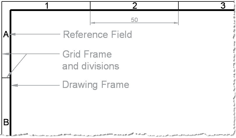
Technical Drawing Standards: Grid Reference Frame.
The typical ‘Engineering’ style drawing border has a grid reference frame drawn into the border. The grid references are used for the location and coordination of details.
Grid Line Weights
The Grid lines themselves are drawn with a 0.35mm line weight. They are spaced 50mm apart from the centring lines. The last two divisions can be whatever size they end up.
Grid References
The grid references start from the top left of the sheet, with letters running vertically from the top down and numbers running horizontally from left to right. On an A4 sheet the grids only need to be drawn on the top and left hand side. The letters I and O are not used – because they could be confused with 1 and 0.
A3 Drawing Border with Grids – Click to enlarge
The Number of Divisions depends on the Size of the Paper
| Paper Size | A0 | A1 | A2 | A3 | A4 |
| Long Side | 24 | 16 | 12 | 8 | 6 |
| Short Side | 16 | 12 | 8 | 6 | 4 |
BS EN ISO 5457:1999+A1:2010 Technical product documentation. Sizes and layout of drawing sheets


Hello Paul,
Can you please guide me as to how I can go about setting up a grid reference on my drawing layout in paper space?. I am using AutoCad 2016. Thank you
Hi Pratik,
That is a big subject to cover in the comments of a blog post!
Try this article:
http://www.mycadsite.com/tutorials/level_2/title_block.htm
Paul
Thanks Paul, very useful info posted here
Paul,
With regards to the exclusion of I and O from gridline lettering, is this a requirement of a particular BS, or is it just construction drawing folklore?
We’re having debates in our office and I can’t find reference in any British Standard (yet)…
B.
Hi Brent,
I and O are specifically mentioned in the BS/ISO standard – Shall NOT be used ;)
Paul
Paul,
That is all boxed up in ASME Y14.1 (M), and I don’t have a copy. I do know that most references I see (and that refer to ASME Y14.1) are established starting from (A1) the lower right corner, at the border. This way all sheets emanate from a common point.
Sorry I can’t be of more assistance.
That’s great – thanks Jon.
Hi Kirsty – does that help?
Paul —
Thanks, that’s what I needed.
Don C.
That’s great!
Thanks Don :)
Paul —
On page http://cadsetterout.com/drawing-standards/grid-reference-frame/ —
Is there a specification for the size of the reference field letters and numbers? Also for the distance between the grid frame and the drawing frame?
If there is a spec, do these sizes depend on the paper size?
Thanks,
Don C.
Hi Don,
The size of the letters/Numbers is 3.5mm. The offset between drawing frame and grid border is 5mm.
These dimensions are constant – only the number of fields changes with the paper size.
Does that help?
Paul
Hi Lambertus,
Not according to BS EN ISO 5457:1999. Do you have a copy?
Paul
Useful info Paul, thank you
What does the BS EN ISO 5457:1999 say about calling out a Grid Reference: is it G14 or 14G – or personal preference??
Hi Matthew, that’s a good question!
It doesn’t address your question directly:
‘The individual fields should be referenced from the top downwards… and from left to right’
So I would go with ‘G14’ – unless anyone is aware of another convention?
Does that help?
Paul
Interesting question from Lambertus – this seems strange to me, as typically if you are dealing with maps or graphs the reference is taken with 0,0 at the bottom left. I have seen it done both ways in drawing templates though.
Does anyone have any knowledge on the logic behind this, or how this compares with ISO? Unfortunately I don’t have access to the BS or ISO at the moment.
Kristy
Hi Kirsty,
Yep – I think that it’s a little weird too ;)
I have a copy of BS EN ISO 5457:1999-2010 that I am referring to, so this covers both BS and ISO standards (explanation here):
http://cadsetterout.com/drawing-standards/whats-in-a-name/
I’m not sure if there is a different convention under JIS and ASME?
Paul
Hi Paul shouldn’t the numbers be counted from right to left and the letters from down to up?