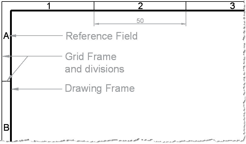
The typical ‘Engineering’ style drawing border has a grid reference frame drawn into the border. The grid references are used for the location and coordination of details.
Grid Line Weights
The Grid lines themselves are drawn with a 0.35mm line weight. They are spaced 50mm apart from the centring lines. The last two divisions can be whatever size they end up.
Grid References
The grid references start from the top left of the sheet, with letters running vertically from the top down and numbers running horizontally from left to right. On an A4 sheet the grids only need to be drawn on the top and left hand side. The letters I and O are not used – because they could be confused with 1 and 0.
A3 Drawing Border with Grids – Click to enlarge
The Number of Divisions depends on the Size of the Paper
| Paper Size | A0 | A1 | A2 | A3 | A4 |
| Long Side | 24 | 16 | 12 | 8 | 6 |
| Short Side | 16 | 12 | 8 | 6 | 4 |
BS EN ISO 5457:1999+A1:2010 Technical product documentation. Sizes and layout of drawing sheets

