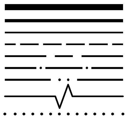
The British Technical Drawing standards allows for three Line weights on each drawing. However, this varies for each drawing discipline.
Engineering drawings only require two line weights, Construction drawings can have up to four Line weights. The Line weights should be in the ratio 4:2:1. The extra line weight for construction drawings is used to represent graphical symbols and is situated somewhere between the ‘Narrow’ Line and ‘Wide’ line.
The acceptable line weights (in mm) that can be used in a drawing are as follows:
0.18 | 0.25 | 0.35 | 0.5 | 0.7 | 1.0 | 1.4 | 2.0
For the nerds among you the ratio between Line weights is 1:√2 (≈ 1:1.4):
You can use which ever group of line weights you like. You should base your choice on the size of paper and copying requirements.
Narrow (thin) |
Graphical symbols |
Wide (Thick) |
Extra Wide |
|
0.13 |
0.18 |
0.25 |
0.5 |
|
0.18 |
0.25 |
0.35 |
0.7 |
|
0.25 |
0.35 |
0.5 |
1.0 |
|
0.35 |
0.5 |
0.7 |
1.4 |
|
0.5 |
0.7 |
1.0 |
2.0 |
if you only want to use two line weights, take the narrow and wide pair from each row.
The default line weight in both Autocad and Inventor is 0.25mm.
The recommended Line weight for the ‘Drawing frame’ (Border) for engineering drawings is 0.7mm. I’m not sure how this fits in!
