How to get started with Autodesk Inventor Stress Analysis
 Welcome along to another guest post on Cadsetterout.com. Thanks very much to Viktor Rask of CADmode.com for this Awesome introduction to the Autodesk Inventor Stress Analysis Environment.
Click here for details of how you can become a guest writer on the CSO Blog!
Have you been trying to figure out the Autodesk Inventor stress analysis add-in for a while, but never quite knew what to use it for? Or why you should even bother learning it!
I’m here to let you know why you should give Autodesk Inventor Stress Analysis another shot and to teach you how to it up and running.
Autodesk Inventor has an add-in named Stress Analysis that is based on FEM (Finite Element Method) (We’ll get into what FEM is in a while!)
The goal of this tutorial is to hold your hand while you try out your first FEA (Finite Element Analysis). There’s also a FEM exercise at the bottom of this page.
I’ve created this step-by-step tutorial so it’s easy to follow but if you need any help just leave a comment!
Click here for more Autodesk Inventor Tutorials.
What is FEM?
We should start off by introducing you to what Finite Element Method (FEM) is. It’s actually not as complex as it sounds. FEM is a numerical calculation method that finds approximate solutions for problems ranging from easy to very complex, the problems are partial differential equations.
What FEM (Finite Element Method) does is to divide a huge problem into smaller and simpler parts. The calculations will then be done on these smaller and simpler parts, one by one. This creates a system of equations that can symbolize the entire problem.
When done in Autodesk Inventor Stress Analysis it literally takes a complex structure and turns it into small parts (this is what the mesh does) and then it solves calculations behind the scenes with a system of equations, this system has different inputs such as constraints, materials and loads. FEM can also be referred to as FEA (Finite Element Analysis).
Step-By-Step Introduction to Autodesk Inventor Stress Analysis
Creating The Geometry to Analyze
Start by creating a regular beam. Try to keep it realistic. I recommend that you get curious and try to do something special with your beam when you’re done with this tutorial!
My beam is 10x2x0.5 (you can use either IPS (English system of Units) or SI (International System of Units), the concept will still be the same).

Don’t worry about the mesh that’s already been done, we’ll get into that later!
Starting The Stress Analysis Study
After you’ve created the model you will go to the environment tab and find this icon:

Here you will find a new set of tools in the toolbar, click on ‘Create Study’ to actually create the stress analysis study.
![]()
Now a window with a bunch of settings will appear but don’t let that startle you! Pick the default settings and press OK.
You should now have a few new settings in your property tree. We’ll be going through these step-by-step.

Assigning Materials for Stress Analysis
When your beam is finished and you’ve gotten your stress analysis study started, your next task is to choose a material.
Your beam could for example be made of wood if you’re a carpenter or structural steel if you’re a construction manager. I’m using steel for the sake of simplicity and usefulness.
To assign material you can use the regular Autodesk Inventor interface or you can override your settings by right-clicking the material tab in your tree. You can also press assign material in the top toolbar.
Choosing Attachment Constraints
Now we will get into some physics, we need to start by creating constraints on the beam. It’s actually quite an interesting process to choose the different constraints because they symbolize how the actual beam might be attached to different structures and with different mechanics.
We will use the fixed constraint which symbolizes a beam that’s basically fixed between two points in space, it could be attached with screws or mounted into a wall. It’s fixed nevertheless.
There are two other constraints you can use which are called pin and frictionless. We will attach the fixed constraint to both sides of our beam. When assigning constraints, you can either assign it to a face, a vertex or a line. In our case we will be choosing the faces.
It’s important to get your constraints correct. If you’re interested in these kinds of simulations I would recommend taking a course in FEM or mechanics of materials.

Simulating The Load To Be Analyzed
When you’ve specified the constraint it’s time to choose what kind of load you want.
If you built a bridge with this beam and a cow would walk across it would it be able to sustain that load?
A cow weighs approximately 500kg (1102lbs).
The load that symbolizes the cow would therefore be the gravitational force of the cow straight down on the beam, we choose a point in the middle which would symbolize that the cow is currently standing in the middle of the beam.
The gravitational constant is 9.81 (SI unit) and we multiply this with the weight of the cow.
500kg * 9.81 = 4980 N (SI unit based calculation)

Contact Constraints Between Parts
Since we’re doing a simple tutorial we won’t have any contacts, these are used if there are more than one part, for example two parts that has a contact surface.
Contacts can sometimes be assigned automatically but you might have to do it manually to be sure that they’re correct.
The Finite Element Analysis Mesh
The larger amount of mesh divisions you request, the harder the calculations become for the Autodesk Inventor Stress Analysis module (This is why computers are used for FEA!)
With a larger number of mesh divisions, we get a more accurate approximation.
For this tutorial we will use the default mesh settings, feel free to fiddle around with them but make sure that your computer can handle it!
This is how it should look by now.

Results
It’s time to see our results :)
Press simulate in the top toolbar and use the default settings.
What we want to check is the Von Mises stress and the displacement, these are usually the most important simulations. Before starting a stress study, you should always try to create goals on why you’re conducting the study, this way it will be easier to see if your design is ok.
So what was the goal that we described before? If our beam could sustain the load of a cow standing on it.
Since this is a relatively basic example it could quite easily be done by hand. FEM with Autodesk Inventor Stress Analysis really shines when it’s used with extremely complex structures.
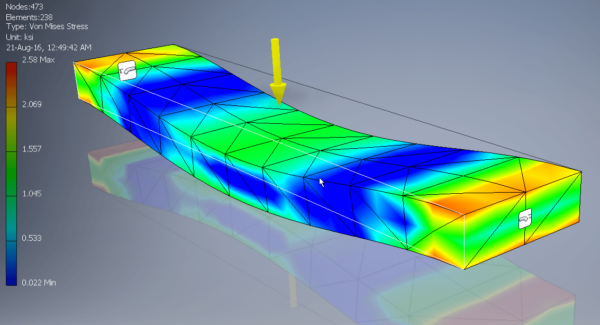
Figure 1 – Von Mises Stress
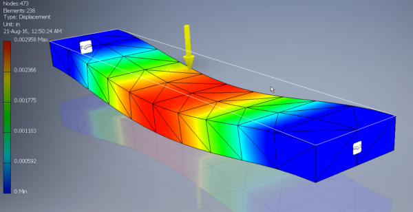
Figure 2 – Displacement
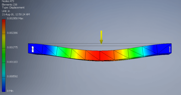
Figure 3 – Displacement Side View
Autodesk Inventor Stress Analysis Exercise
Use the Autodesk Inventor Stress Analysis module to work out how the results would differ if you only had a fixed support (constraint) on one face and the load was put on the beams non supported side.
If you need any help you can send me an email at viktor[at]cadmode.com with the subject line “CSO FEM Exercise”.
When I started to learn CAD I had trouble finding practice material, fast forward a few years and a friend of mine had the same problem. This same friend kept bugging me to give him schematics so he could have something to practice on. This led me to create CAD Mode and write the e-book “Learn & Improve Your Skills: 101 CAD Exercises”. I’ve now been working with CAD for 5 years and learnt a lot in that time, I love teaching and I’m ready to share my knowledge.
Click here to get 101 CAD Exercises
Viktor Rask
Founder of CAD Mode
Hello, I am wondering, the weight of the bridge itself add more force downward, right? Is that automatically accounted for by the software? I can use the gravity feature on the tab but is that weight a point load or UDL?
Hi Roshan,
Yes, the FEA solver uses the geomerty and material proerties to account for the physcal proerties of the component.
Hello,
when I get the result from FEA.
How can I understand what is the Max. load for beam to sustain?
Example:
1) Load: 5000 N, Results are showing: Min. 1237 N, Max. 3864 N
2) Load: 1000 N, Results are showing: Min. 321 N, Max. 736 N
I steel don’t know can I put 1000 N or 5000 N on a beam.
Hi Aleksander,
I recommend that you post your question on the Autodesk Inventor Forums:
https://forums.autodesk.com/t5/inventor-forum/bd-p/78
Not only will you get a quicker and more comprehensive answer than I can give, but the solution will be logged for future Autodesk Inventor users to learn from.
If you do write a post on the forum, remember to come back here and post a link in reply to this comment so that we can follow your progress!
Thanks very much,
Paul
Hi I am interested in the ‘Pressure loading’ part
Would this help to see if a pipeline part is suitable at a set internal pressure and temperature for the Fluid/Steam/Gas passing through it?
Hi David,
Yes, you can calculate pressure loading with Inventor FEA.
Paul
great work and thanks for the valuable documented blog ,it was really helpful